Raymarching meets dyalog APL
By bl0v3 • 13 minutes read •
NOTE: Since this commit/relase multithreading is now officially supported. Though this page was written before I added support for that so keep that in mind when reading this page.
APL IS NOT MEANT TO BE USED FOR SUCH TASKS!!! It simply is not the language one should choose to perform such a task. With that being said. Keep in mind that as this was just a hobby weekend project there are various flaws and shortcomings to watch out for
- Performance isn’t too good as until I fix some things also multi-threaded execution contexts
aren’t supported yetare supported now - Ray tracing / Ray marching is inherently slow thus such algorithms rarely used for real-time graphics but rather, for pretty much all CGI you’d see in your average movie made in the more recent years
- There may be some flaws as I haven’t gotten the chance to take thaaaaat good of a look at APL specifically dyalog APL yet
- This project essentially served to gain a better understanding of the language after all
WORK IN PROGRESS!!! (while it does work finetuning still needs to be done and the code needs to be re-structured in some ways partially because I learned some new things about apl while writing this)
code
source code
As for now I only provide build expression through nix which alongside the source-code are located at this github repository.
NOTE: Since this commit/relase multithreading is now officially supported. Though this page was written before I added support for that
running it yourself
Currently the build targets/instructions are supplied via (nix)[https://nixos.org/] as it provides a quick, declarative and reproducible way to build this project but the build instructions can easily be derived from the flake.nix file located in the root directory of the repository linked above.
Thus:
running under nix
# output will we placed in cwd as rendering.png
(take a look at the repositories README.md or flake.nix file for further targets/runners)
implementation details
so how does it work?
With ray marching works pretty similar to ray tracing, but instead of checking
if our ray intersects with object’s exposed surface through the means of algorithms
such as the Möller–Trumbore intersection algorithm. We instead use something called signed distance functions or short “SDF” ’s. Essentially signed distance functions/SDFs are functions taking a given point in space p as their input parameter returning the distance from the given point p and the geometry it defines.
For example the SDF for a sphere would look something like this (in GLSL)
float
Essentially taking the length of a point spanned from one point to another. As in some point along the ray originating from our camera subtracted by the radius of a sphere. Tells us how far away that sphere (with the given radius) is from the supplied point (passed as vec3 p in this example).

A possible implementation of said SDF in APL may look like this: (Taken from my implementation):
ball_sdf←{ (length ⍵) - ⍺ }
with the length function being supplied through:
⍝ ⍺ =2 would mean the squareroot
sqrt←{⍵*÷⍺}
length←{2 sqrt (+/{⍵*2}¨⍵)}
NOTE: As its called signed distance function instead of just distance function or usigned the values returned make use of (signed number representation)[https://en.wikipedia.org/wiki/Signed_number_representations].
What this means in practice is assuming lets say we’d run it against a point contained within the sphere defined by the function above:
(0.5) ball_sdf((0)(0)(0))
we’d get a negative return value of ¯0.5
using a point such as (0.28 0.28 0.28) instead which is pretty much on the edge
provided by the diameter/radius of said sphere like:
(0.5) ball_sdf((0.28)(0.28)(0.28))
wed get ¯0.01502577388 as the length of (0.28 0.28 0.28) which roughly equates to 0.48497....
What we can essentially derive from that information is:
- if
sdf(p)is positive, p lays outside ofsdf - if
sdf(p)is negative, p lays withinsdf - if
sdf(p)is very close to +-0 as in lets saysdf(p) < 0.0001plays on the edge or withinsdf()
Ok but how do we go from having a SDF to actually approximating where and if object is hit=visible?
Luckily that is quite simple to do. First we need to define some variables though
Assuming the function res supplies the horizontal and vertical resolutions as (x y)
res←↑(get_res drawer ( 0 0 ))[2]
xres←(res)[1] ⋄ yres←(res)[2]

cam_origin←(0 0 ¯1)
As we now have the dimensions of image/frame we intend to render. We map each pixel onto a 2 dimensional plane
to then cast a ray through each respectively mapped pixel coordinate (x,y). There are various ways to represent our
pixel/plane-coordinate mapping. In my approach I first span a map going from (0,0) to (1,1)
and offset that to (-0.5,-0.5) to (0.5) (0.5) as I prefer that notation.
One way of implementing this would be through
xy←{((⍳(xres))-1)⍵}¨((⍳(yres))-1)
_uv←{(⊃⍵[1]÷xres) (⍵[2]÷yres)}¨xy
uv←_uv-0.5
This illustration further outlines the process underwent

Before we can then run our SDF’s against the rays cast through the 2d pixel/plane-coordinate mapping one should also apply the so called aspect ratio through:
uv←{⊃((⍵[1] ÷ (xres ÷ yres)) ⍵[2])}¨uv
uv_vecs ← ⊃,/{y←⍵[2] ⋄ {⍵ (-y)}¨(⊃⍵[1]) }¨uv
With the pixel/plane-coordinate mapping in place and the aspect ratio being corrected. Generating rays is as simple as:
{
	x←⍵[1]
	y←⍵[2]
	cam_dir←norm x y 1
    rgb cam_dir t
}¨uv_vecs
The code above would emit an array of normalized directional vectors with the respective (x y) pixel/plane-coordinate mapping being apply the the vectors x and y directional components. This along with the camera origin
would provide the basis for our camera model.
In my renderer the function rgba lays the basis to converting ray vectors to actual color values.
Now casting the ray is done using the abstract below
rgb cam_dir t
where cam_dir is the vector with the directional components described above and t denoting time (while not implemented yet one could reference the t variable if one wanted to render an animated scene).
Though you may ask yourself: why is it called ray marching? Like where is the actual “marching” taking place? And why do we even need to march in the first place? Isn’t using that SDF by itself enough?
Well essentially what would happen if you had lets say 2+ objects and the ray would come quite close to one object initially but then still pass by. Not actually intersecting the objects surface and maybe hit another object. As the SDF would still return the distance of the closest object (See below)
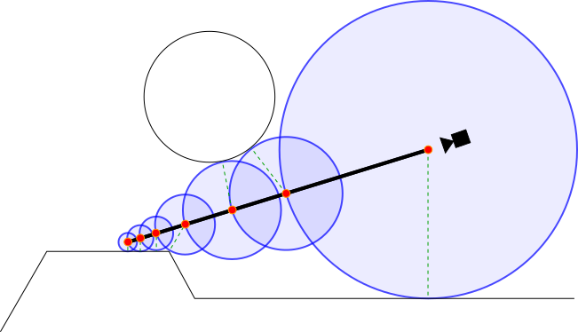
(TODO add a better ilustration)
this wouldn’t tell us too much. The SDF by itself doesn’t respect the rays direction but just provides a mere distance estimate. As you can see the distance it determines can represented in a fashion resembling the radius of a sphere. Meaning it only tells us the distance from one point to another point but not if it actually lays along a ray.
In order to accommodate for this issue. We essentially to approach the point we plan intersect in a step-wise manner. The smaller the lowest possible distance grows, the smaller further steps undertaken would be. If the distance is approaching 0 (getting very close to it) . We’d register that as a hit. Otherwise we would step on until either the max step count is reached or the maximum distance is exceeded.
The marching function is called from the rbg function described above, at the time of writing this it looks like this:
⍝ ⍵ = [ cam_dir time bg ]
rgb←{
    cam_dir←⊃⍵[1]
	time←⊃⍵[2]
	d←(( 0 cam_origin  cam_dir 35 100) march 0)
	hit←d[1]

	⍝ 	phong ( total_dist , ro , rd , obj)

	hit: phong ((d[2]) cam_origin cam_dir (d[3]))
	⍝ not hit (render background)
	(sky cam_dir[1] (0 ⌈ ((cam_dir[2])+0.12)))
}
Essentially d←(( 0 cam_origin cam_dir 35) march 0) is where the magic happens. Our march function will march
along cam_dir vector, starting from cam_origin. The 35 denotes the maximum of 35 steps which will be taken. Of course that can be adjusted. For example rendering reflections should get away using a lower maximum step count, as less precision is needed there I figured. 100 denotes the maximum distance objects can have from the ray origin (camera) . So we render objects up until the vector length of 100.0 from the camera. While technically not needed, if we omitted this wed always take 35 or whatever out max step count is set to until giving up. This reduces the amount of unnecessary computations needed. The first argument of march is the distance stepped so far. We initialize this with 0, as march internally calls itself in a self referencing fashion with the distance value increasing when its supplied as the first parameter in further self referencing calls to march. The argument on the right most side of march is the stepcount. We also initialize this with 0 as march will every time it calls itself increment that by one.
march first return value returns either 0 or 1 as in (hit,...) which is inspected before accessing the further
return values, such as the distance d[2] or the respective id of the object hit d[3]. Further processing of march’s
return values is bound to that first hit value. Since if march never hit anything, we couldn’t return anything in these fields
and thus it would be pointless to work with them.
Assuming hit=1 as in true wed call the phong function which would apply the phong shading model taking as its last parameter the id of the object hit. As knowing that we can from within phong apply different “material” properties by using different light absorption/reflection attributes in accordance with the phong shading model.
If nothing was hit the sky function will be called returning the r g b components of the background for the given point.
Now lets dissect the march function to gain a better understanding of it:
⍝ ⍺ = [ total_dist , ro , rd , max_steps, max_dist ]
⍝ ⍵ = stepcount
march←{
	total_dist ← ⍺[1]
	ro ← ⊃⍺[2]
	rd ← ⊃⍺[3]
	max_steps ← ⊃⍺[4]
	max_dist ← ⊃⍺[5]

	r ← sdf ( ro + rd × total_dist )

	dist ← r[1]
	obj  ← r[2]

	⍝ if we exceeded the maximum amount of steps return 0
	⍝ AND we exceeded the maximum distance from the ray origin=( eg cam pos/point of reflection) return 0

	⍝ TODO use dist to simulate fog  by adding some fog color value based on the distance
	⍵<max_steps ^ dist < max_dist: {
		dist < epsi: (1 (dist + total_dist) obj )
		( (dist + total_dist) ro rd max_steps max_dist) march ⍵
	} ⍵+1
	(0 0)
}
I believe the abstract is pretty self explanatory but in essence r ← sdf ( ro + rd × total_dist ) is of most
interest. All SDF’s at least take one parameter p which denotes the point in space the signed distance function
returns the respective distance to. In order to “march” we must progress our directional vector rd derived
through the pixel mapping above by the total_dist factor to get the current distance to run our intersection-range
checks against. This needs to be added to the camera origin positional vector ro. We could also leave ro out but then our camera would be restricted to being located at 0 0 0. But to deliver more flexibility here and as the march function is used in other places within this program
(for example for marching along reflection rays which start from the surface we reflected from) . So its generally
better to add ro here.
We could for example set r to the ball_sdf←{ (length ⍵) - ⍺ } function as showcased early on in this article.
⍵ denotes the point p in this case ro + rd × total_dist while ⍺ represents the radius of the sphere.
Were not limited to a single sphere sdf. Of course one could also combine multiple sdf’s through use of the ⌊ > minimum operator.
For example showing 2 spheres. One in the center of our scene and one located at y=+1 through defining/calling:
(ball_sdf (p - (0 0 0)) ⌊ (ball_sdf (p - (0 1 0))
This works as it would return the distance to the sphere closest to us. (-sdf1) ⌈ (sdf2) could be used
to carve out the first geometry defined by the first sdf from the second one NOTE: this “-” sign is required here. Likewise
using (sdf1) ⌈ (sdf2) max would instead return only the points where sdf1 intersects with sdf2. There are lots
of tricks that can be used when working with signed distance functions. But it should already be clear that even with
just min and max and + and - one can compose some pretty complex geometry.
Now I will focus on the call to the phong function seen before in rgb. rgb has the section:
hit: phong ((d[2]) cam_origin cam_dir (d[3]))
which essentially runs phong with the parameters
⍝ ⍵ = [ total_dist , ro , rd , obj]
The start of phong is structured like this:
⍝ ⍵ = [ total_dist , ro , rd , obj]
phong←{
	total_dist←⊃⍵[1]
	ro←⊃⍵[2]
	rd←⊃⍵[3]
	obj←⍵[4]

	p←ro + rd × total_dist


	l1←{
		ambient_color←checkers_ball p
		diffuse_color←0.5 0.5 0.5
		specular_color←0.1 0.1 0.1
		alpha←0.7
		light_intensity←⍵

		ambient_color diffuse_color specular_color alpha light_intensity
	} 0.5

    ⍝ ... further lights

	lightPos←3 3 0 ⍝ hardcoded here but could ofc be passed  via ⍵[5]
l1 defines a light locally. In my case phong defines l1 - l7.
Instead of trying myself at explaining what
ambient_color←checkers_ball p
diffuse_color←0.5 0.5 0.5
specular_color←0.1 0.1 0.1
does. I will just include a picture that gets the point across

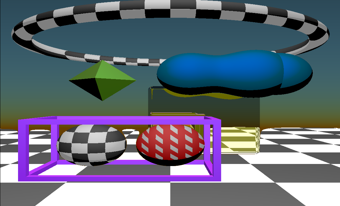
following lightPos seen above comes
⍝ checkered ball
⍵=scene_obj1_ball: l1 phongLight p ro
⍝ octahedron
⍵=scene_obj2_octa: l2 phongLight p ro

⍝ blob
⍵=scene_obj3_melted_balls: l3 phongLight p ro

⍝ floor
⍵=scene_obj4_floor: (l4 phongLight p ro) + (4 checkers ((p[1]) (p[3])))

⍵=scene_obj5_frame: (l5 phongLight p ro)

⍵=scene_obj6_ball: (l6 phongLight p ro) + ( 0.5 × (0.11 checkers ((p[1]) (p[2]))))

⍵=scene_obj7_torus: (l6 phongLight p ro) + ( 0.5 × (0.22 checkers ((p[1]) (p[2]))))

⍵=scene_obj8_rounded_box: reflective_material ( p rd ro scene_obj8_rounded_box l7)
assuming of course the scene_objX_NAME-type variables are defined somewhere accessible.
In my case globally like shown below. Note that there is no catchall/default expression.
I intentionally chose this so I don’t accidentally forget handling each defined object individually.
But you could of course just write something like:
    ⍵=scene_objX_NAME: (l_X phongLight p ro)
    (l_default phongLight p ro)
With (l_default phongLight p ro) being applied for any unmatched object. phongLight
takes the as its left-side parameter whats defined above by l1-l7 and as the parameters on the
right p and ro. ro in this case provides the position of the camera and p being the point on a surface
march detected an intersection with. Based on that information, phongLight returns a color
in the (r g b) (float float float) specification. Please note that as ⍵=scene_obj8_rounded_box is
a little special special I will document it later on. As its the only object with reflective properties in the scene.
scene_obj1_ball←1
scene_obj2_octa←2
scene_obj3_melted_balls←3
scene_obj4_floor←4
scene_obj5_frame←5
scene_obj6_ball←6
scene_obj7_torus←7
scene_obj8_rounded_box←8
Knowing the object id in ⍵ is quite useful here, as it allows us to apply phong shading or even textures/reflection
properties on various objects individually. If we were to omit it, wed either have to calculate it again by throwing p
back into in the sdf’s again or we would have to assign the same texture and phong shading properties to every object.
So now lets look at phongLight:
The picture below should provide some hints of what is going on in there
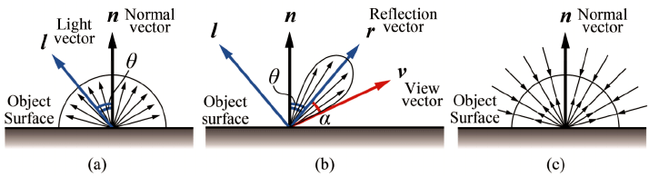
⍝ ⍺ = [ ambient_color(rgb), diffuse_color(rgb), specular_color(rgb), alpha, light_intensity ]
⍝ ⍵ = [ p ro ]
phongLight←{
p←⊃⍵[1]
ro←⊃⍵[2]
⍝ TODO REMOVE 0.5 (DEBUG)
ambient_color←(⊃⍺[1]) × 0.5
diffuse_factor←⊃⍺[2]
specular_factor←⊃⍺[3]
alpha←⊃⍺[4]
light_intensity←⊃⍺[5]
⍝ estimate the normal vector at point p on the surface
n ← estNormal p
⍝ light position ( TODO don't hardcode up here )
light_pos←((0) (3) (1))
⍝ vector between the point on the surface and the light position
l← norm ( light_pos - p)
⍝ vector between the point on the surface and the view/camera/etc vector
v← norm ( ro - p)
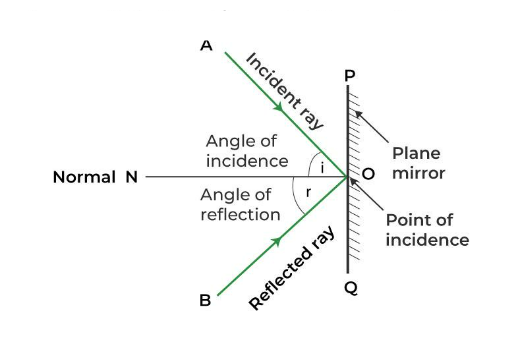
⍝ vector reflecting the light-surface vector on the estimated surfaces normal vector
r← norm ( (-l) reflect n )
⍝ dot product of both
dotln ← l dot n
dotrv ← r dot v
⍝ the light doesn't hit the surface at any relevant angle
dotln < 0.0: 3 ⍴ 0.0
c ← ambient_color + {
⍝ angle not in range for specular effect, just apply diffuse color
⍵ < 0.0: diffuse_factor × dotln
⍝ angle in range for specular effect, apply diffuse and specular colors
diffuse_factor × dotln + specular_factor × ( dotrv × alpha )
} dotrv
light_intensity × c
}
Essentially based on what angle we look at the surface from and the position of a light we can determine if a specular effect should be present or rather just the diffuse lighting effect alone. Or if the light sources rays never even hit the object in the first place. Based on if any of the 3 cases (not hit, hit diffuse, hit specular) we apply these effects
Now to scene_obj8_rounded_box: which is special in the sense that it doesn’t just apply phong shading
but also simulates a reflective surface.
What essentially happens here is that if obj=scene_obj8_rounded_box: reflective_material, meaning the rounded box “8”
got hit by a ray cast from the camera. Instead of applying phong shading like we do with the other objects.
Whats being done here is that similar to how its done when applying phong shading. We take into account from what angle were
looking at the object from. Using the estimated normal vector of the point on the surface the camera ray
is pointing at and the view angle we can reflect the ray accordingly.
So knowing what the vector/ray direction after being reflected allows us to do the following: We essentially do the same as what we did when casting rays from the camera upon non reflective objects. But instead of the ray origin being the camera and the ray direction being determined through which pixel on our plane it goes, the ray origin is the position our ray originating from the camera hit the reflective surface at. Likewise we use the reflected directional vector as our new directional vector.
One could think of it roughly as us moving the camera to the point were reflecting from . using
this new information we then undergo the marching loop once again by calling the march function. Note that the maximum
step count was reduced to 20 and the maximum distance to 40 as reflections generally need less accuracy.
IMPORTANT DETAIL: note the line specifying ref_surface_p ← ref_surface_p + ref_surface_n × 0.005 makes up
a VERY!! very important detail. Basically what happens here is that we shift the origin we use when casting the reflected ray by a tiny bit forward (towards the normal vector of the surface) to avoid it intersecting with itself.
Whats left is performing phong shading on the object initially hit not the reflection. To then combine that
with the color values returned after performing the reflection. As otherwise wed have a perfect mirror
though (you likely couldn’t tell its a mirror). So in order to be able to tell it apart as a reflective surface
it can’t perfectly reflect everything and needs to perform some sort of modification to the colors it reflects. As for now l7 gives it a slightly yellow tint.
The line doing that job is essentially col_obj_self← (light phongLight ref_surface_p ro )×0.3 and at the return segment
	hit: ((t ref_reflected_final)×0.7) + col_obj_self
        	⍝ nothing hit, thus apply background accoring to the reflected vectors orientation
        	((sky (ref_reflected_rd[1])  (0 ⌈((ref_reflected_rd[2])+0.12)))×0.5) + col_obj_self
reflective_material←{
	ref_surface_p ← (⊃⍵[1])
	ref_view_rd ← (⊃⍵[2])
	ro ← (⊃⍵[3])
	obj_self← (⊃⍵[4])
	light ← (⊃⍵[5])

    	⍝ normal vector of the point we hit the surface at
	ref_surface_n ← estNormal ref_surface_p

    	⍝ IMPORTANT !!! V
    	⍝ slightly offset the origin to cast the reflected ray from in the direction of the reflecting surfaces
    	⍝ normal vector (which will always point away from it)
	ref_surface_p ← ref_surface_p + ref_surface_n × 0.005

    	⍝ reflect the camera to reflective surface vector using the surfaces normal vector at that position
	ref_reflected_rd ← norm (    ref_view_rd reflect ref_surface_n )


    	⍝ initiate raymarching once more but this time starting from the reflecting surface
    	⍝ using a slightly reduced  step count/max distance
	ref_reflected_final  ← ( 0 ref_surface_p ref_reflected_rd 70 150) march 0

	⍝ 1 if the reflected ray hit anything, otherwise 0
	hit←(ref_reflected_final[1])
	t←{
		dist←⍵[2]
		obj_is_self← (⍵[3])=obj_self
        	⍝ object intersected with itself ( should never happen for now just color it in a vibrant
        	⍝ green soits easy to debug or maybe throw an exception
		obj_is_self: ( 0 1 0)
            		⍝object didn't intersect with itself, apply phong shading at the point the reflection ray hit at
            		phong (dist ref_surface_p ref_reflected_rd (⍵[3]))
	}
	col_obj_self← (light phongLight ref_surface_p  ro )×0.3

    	⍝                      V phong shading at the point the reflection hit at
	hit: ((t ref_reflected_final)×0.7) + col_obj_self
        	⍝ nothing hit, thus apply background accoring to the reflected vectors orientation
        	((sky (ref_reflected_rd[1])  (0 ⌈((ref_reflected_rd[2])+0.12)))×0.5) + col_obj_self
	⍝ TODO ^ instead of using these hardcoded values allow the user to specify the factor of what
	⍝ rgb components get reflected more and make it bound to distance. For now this is too
	⍝ enhance obj reflecitons while not reflecting the background too much but thats ofc just a hack
}